
A Polymer Surge Arrester protects electrical equipment from damaging overvoltage. It is commonly installed on medium-voltage poles, substations, transformers, and industrial distribution systems. Its polymer housing is lightweight, weather-resistant, and less likely to shatter than traditional porcelain. That difference matters during a severe fault.
Inside the arrester, metal-oxide varistor blocks respond rapidly to rising voltage. Under normal conditions, they carry only minimal leakage current. During a lightning strike or switching surge, their electrical resistance falls sharply. The surge current then flows safely toward ground. Voltage across the protected equipment is reduced. The process happens within microseconds.
Surge-protection specialist David W. Deno describes the central principle this way: “An arrester limits overvoltage; it does not eliminate the surge.” This distinction is essential. A Polymer Surge Arrester cannot replace proper grounding, insulation coordination, or effective system design. It is one part of a complete protection strategy.
A field inspection may reveal cracked weather sheds, loose terminals, polluted surfaces, or poor grounding connections. Small details can decide whether protection works. Polymer materials also age under ultraviolet exposure, moisture, heat, and electrical stress. Their performance is strong, but never permanent.
The subject is less simple than a product label suggests. Installation quality matters. Selection matters more. This article explains what a Polymer Surge Arrester is, how its internal components operate, and why correct coordination protects transformers, cables, and other valuable equipment. Some assumptions deserve rechecking, especially when real networks differ from laboratory conditions.
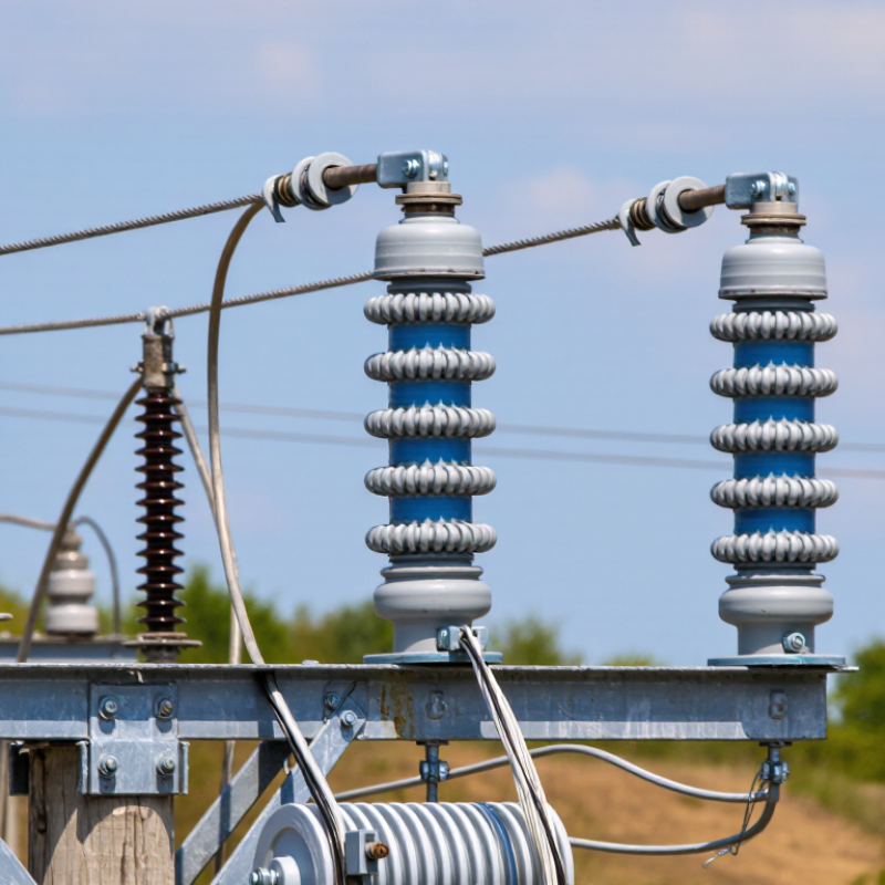
A polymer surge arrester is a protective device for medium- and high-voltage systems. It limits temporary overvoltage caused by lightning or switching events. Inside, zinc-oxide varistor blocks remain highly resistive during normal voltage. During a surge, their resistance drops sharply. Current then flows safely toward earth, protecting transformers, cables, and other insulation.
The polymer housing provides external insulation and sheds water from the surface. Its flexible, lightweight structure can also reduce handling risks during installation. IEC 60099-4 defines performance requirements for metal-oxide surge arresters. CIGRE Technical Brochure 549 highlights the importance of energy capability, ageing tests, and coordination with system insulation. These details matter in real substations, where a few metres of cable can change surge behavior. Field conditions are messier than laboratory curves.
The purpose is not to stop every surge. It is to keep the remaining voltage below equipment withstand levels. A common mistake is selecting an arrester only by system voltage. That approach can fail. Temporary overvoltage, discharge energy, pollution, altitude, and earthing resistance also require review. Protective distance must be checked carefully, especially near transformer bushings.
Tips: Confirm the continuous operating voltage first. Check leakage current and thermal stability records. Inspect housing sheds for cracks, contamination, or damaged seals. Keep test certificates traceable to IEC or equivalent requirements. In practice, installation drawings deserve as much attention as the arrester itself.

A polymer surge arrester is a compact device that limits dangerous voltage surges. Its active core usually contains zinc oxide varistor blocks. These blocks respond to voltage changes without requiring a spark gap. At normal system voltage, they allow only a small leakage current. During lightning or switching surges, their resistance drops sharply. They channel excess current toward ground. The protected equipment then experiences a lower voltage. After the disturbance, the blocks return to a high-resistance state. It happens quickly. This electrical behavior depends on stable contact pressure and accurate varistor quality.
The outer structure normally includes silicone rubber sheds, a fiberglass-reinforced polymer rod, metal end fittings, and sealing interfaces. Silicone rubber helps repel water and supports reliable outdoor insulation. The sheds also increase the creepage distance along the surface. The fiberglass rod provides mechanical strength during wind, vibration, and installation work. Metal fittings connect the arrester to the line and grounding system. Some designs include grading rings to control electric-field stress near the terminals. In field maintenance, technicians should inspect for cracks, loose seals, tracking marks, or a chalky surface. Moisture can enter through small defects. That detail matters. The design is not flawless; contamination, heat, and aging still change performance. Routine testing and careful installation remain necessary.
A polymer surge arrester responds within microseconds when an overvoltage reaches a power line. Its metal-oxide varistor blocks normally at system voltage. During a surge, its resistance falls sharply. This creates a safer path for impulse current toward earth. The protected equipment then sees a limited residual voltage, rather than the full transient peak.
The response is tested under the 8/20 microsecond current impulse specified in IEC 60099-4. CIGRE Technical Brochure 549 also identifies thermal instability, moisture ingress, and ageing as important arrester failure factors. The polymer housing adds practical protection. Its sheds lengthen the leakage path and help maintain insulation during rain, dust, or salt exposure. Pressure-relief features can reduce damage if internal heating becomes severe.
Small details matter. Cable length changes the actual voltage at the equipment terminal. Poor grounding can also raise the residual voltage, even when the arrester itself performs correctly. A field reading may look normal after one event. That does not prove full service life remains. Maintenance teams should inspect leakage-current trends, housing cracks, loose connections, and contamination. The honest limitation is simple: polymer does not make an arrester indestructible. Its performance depends on correct voltage selection, grounding, installation distance, and repeated surge duty.
A polymer surge arrester uses metal-oxide varistors (MOVs) to limit transient overvoltage. During a representative 10 kA, 8/20 μs lightning-current impulse, the MOV changes from a high-resistance state to a low-resistance state, diverting surge current to ground and clamping the voltage across protected equipment.
The chart shows a representative arrester response rather than a universal rating. The applied surge rises rapidly, while the arrester voltage is limited to a lower residual level as surge current is diverted. Actual values depend on system voltage, MOV configuration, impulse waveform, and arrester energy rating.
What Is a Polymer Surge Arrester and How Does It Work?
A polymer surge arrester protects electrical equipment by limiting excessive voltage. Its core uses metal-oxide varistor blocks. Under normal system voltage, these blocks remain highly resistive. Only a small leakage current flows through the arrester. During a lightning or switching surge, resistance falls sharply. The arrester then diverts current toward ground and limits the voltage across transformers, cables, and other equipment.
The timing is extremely short. A standard 8/20 microsecond impulse represents a common surge-test waveform in IEC 60099-4. The same standard recognizes nominal discharge currents, including 2.5, 5, 10, and 20 kiloamperes, depending on the arrester class. IEEE testing guidance also evaluates residual voltage, energy capability, and repeated impulses. Lower residual voltage generally means stronger equipment protection, but coordination remains essential. A poorly selected arrester can still leave dangerous stress.
The polymer housing adds practical protection. Its flexible, sealed surface resists moisture and reduces contamination-related flashover risk. Field inspections should still check cracks, tracking, loose connections, and unusual leakage current. Real installations age differently. Temperature, pollution, and repeated surges matter. A simple catalog value cannot describe every site. That is an important limitation. Reliable protection depends on correct voltage rating, grounding, insulation coordination, and periodic condition assessment.
| Operating Condition | Typical Electrical Stress | Arrester State | Current Through the Arrester | Voltage Across the Arrester | Protection Process | Expected Result |
|---|---|---|---|---|---|---|
| Normal system operation | 11 kV distribution system; approximately 6.35 kV RMS phase-to-ground | High-resistance standby | Very small capacitive and resistive leakage current, commonly in the microampere-to-low-milliampere range | Close to the normal phase-to-ground system voltage | Metal-oxide varistor blocks significant conduction while continuously monitoring the line voltage | Normal power flows to the load without material energy absorption by the arrester |
| Continuous operating voltage limit | Representative MCOV: 8.4 kV RMS for a medium-voltage arrester used on an 11 kV system | Stable and non-linear | Leakage remains limited when the applied voltage is below the continuous operating voltage limit | Voltage remains within the arrester’s intended continuous-duty range | The polymer-housed arrester remains connected between the line and ground without interrupting normal service | Reliable long-term operation, provided the system voltage and grounding arrangement are correctly selected |
| Temporary overvoltage | Approximately 1.2–1.4 per-unit voltage caused by faults, load rejection, or grounding conditions; duration may range from cycles to seconds | Increased conduction | Higher leakage current than during normal operation | Voltage is limited, but the arrester may heat if the overvoltage is excessive or prolonged | The varistor conducts progressively as voltage rises; its thermal capability and temporary-overvoltage rating determine safe withstand time | The system may remain protected if the temporary overvoltage is within the arrester’s specified capability |
| Lightning or switching surge arrival | Fast transient impulse; a common test waveform is 8/20 microseconds | Low-resistance conduction | Surge current may range from several hundred amperes to several kiloamperes | Representative residual voltage: approximately 20–35 kV for a medium-voltage unit, depending on design and test current | The zinc-oxide varistor changes rapidly from a high-resistance state to a highly conductive state and diverts surge current to ground | Equipment insulation is exposed to a lower, controlled voltage than the incoming surge |
| Moderate switching surge | Typical impulse current of approximately 0.5–2 kA, depending on the network and switching event | Controlled conduction | Hundreds of amperes to a few kiloamperes | Usually below the arrester’s lightning-impulse residual-voltage level | The arrester absorbs and diverts transient energy while limiting the crest voltage at the protected equipment | Reduced risk of insulation stress caused by circuit-breaker operation, capacitor switching, or fault clearing |
| High-current lightning discharge | Impulse current can reach several kiloamperes; actual severity depends on exposure, shielding, and grounding | Heavy conduction and energy absorption | Common arrester test levels include 5 kA or 10 kA using an 8/20 microsecond current waveform | Clamping voltage rises with discharge current because the varistor has a non-linear voltage-current characteristic | The arrester conducts the impulse to ground while the polymer housing provides external insulation and environmental sealing | Transient voltage is clamped to a level selected below the protected equipment’s insulation withstand level |
| After the surge ends | System voltage returns to its normal operating value | Returns to high-resistance standby | Surge current stops; only normal leakage current remains | Returns close to the system phase-to-ground voltage | The varistor stops conducting heavily without requiring a spark gap to extinguish an arc | Protection is automatically restored for subsequent transients, assuming no thermal or electrical damage occurred |
| Severe or repeated overload | Excessive temporary overvoltage, repeated high-energy surges, or an incorrectly selected arrester | Thermal stress or failure condition | Persistent high leakage current may produce internal heating | Protection performance can deteriorate, and the arrester may no longer clamp voltage correctly | An integrated disconnector may separate a failed unit from the system; the polymer housing is designed to reduce explosive fragmentation compared with brittle housings | The arrester must be inspected and replaced after confirmed failure or when diagnostic indicators show unacceptable degradation |
| Grounding and installation path | Short, low-inductance connection between the line terminal, arrester, and earth | Essential for effective protection | Surge current is directed through the arrester and grounding conductor | Every metre of extra lead length can add inductive voltage during a fast surge | Correct phase-to-ground connection, short leads, appropriate clearances, and a low-impedance earth path minimize the voltage appearing at the equipment | Better coordination between arrester residual voltage and the protected equipment’s insulation withstand rating |
Polymer surge arresters protect electrical equipment from lightning and switching surges. They are commonly installed near transformers, cable terminations, generators, and overhead line connections. Their polymer housing surrounds metal-oxide varistor blocks, which conduct excess voltage safely toward ground. During normal operation, the arrester remains highly resistant. When a surge arrives, its resistance falls within microseconds.
This response helps limit stress on insulation, windings, and control equipment. Polymer housings are lightweight, hydrophobic, and less likely to shatter than traditional porcelain designs. They also perform well in coastal, industrial, and heavily polluted environments when properly selected. Installation still matters. A poorly bonded grounding lead can undermine an otherwise excellent arrester.
Maintenance should include visual inspections after severe storms and scheduled equipment outages. Look for cracks, swelling, discoloration, loose connections, damaged seals, or signs of tracking. Check the grounding conductor for corrosion and confirm that connections remain tight. Infrared scans can reveal unusual heating, while leakage-current monitoring may identify gradual varistor deterioration. A clean-looking unit can still be aging internally.
Environmental exposure deserves attention. Ultraviolet radiation, salt deposits, moisture, and chemical pollution can accelerate surface damage. Cleaning methods must follow the equipment manufacturer’s technical guidance and site safety rules. Inspection records should include photographs, readings, weather conditions, and corrective actions. No maintenance plan is perfect. Reviewing missed warning signs after a failure can improve future decisions.
Precision Cable Assemblies
16830 Pheasant Drive
Brookfield, WI 53005
Phone: 262-784-7887
Fax: 262-784-0681