Rotary Actuator Symbols look small, but they control how engineers interpret motion, ports, and energy paths. A circular arrow on a schematic may indicate rotation, direction, or an actuator function. The surrounding lines matter just as much.
The IEC 60617 graphical symbols database provides internationally recognized symbols for electrotechnical diagrams. ISO 1219-1 defines graphical symbols used in fluid power systems, including pneumatic and hydraulic components. These standards support consistent documentation across design offices, factories, and maintenance teams. In practice, a technician may identify a rotary actuator from a symbol before seeing the machine itself. A mislabeled port can still create confusion.
Automation continues to expand the need for clear drawings. The International Federation of Robotics reported 541,302 industrial robot installations worldwide in 2023. Many robotic cells use rotary actuators for gripping, indexing, positioning, and tool rotation. Each application depends on readable schematics. The wrong symbol can waste valuable troubleshooting time.
This guide explains the Top 10 Rotary Actuator Symbol Types Explained through practical visual details. It covers pneumatic, hydraulic, electric, double-acting, spring-return, and position-controlled forms. It also considers arrows, shafts, pressure lines, electrical terminals, and limit-switch markings. Symbols are not always perfectly consistent across software libraries. That deserves attention.
Engineers should verify the drawing against ISO, IEC, ISA, or project-specific conventions. A familiar icon may still be incomplete. Field experience shows that context often determines the correct interpretation. The goal is not memorization. It is safer, faster, and more reliable communication.
Top 10 Rotary Actuator Symbol Types Explained
Rotary Actuator Symbols: Purpose, Structure, and Reading Principles
Rotary actuator symbols translate movement into a compact visual language. They show rotation, torque, flow direction, and control method. In practical schematics, I read the symbol before checking the component list. This habit prevents costly wiring and piping errors.
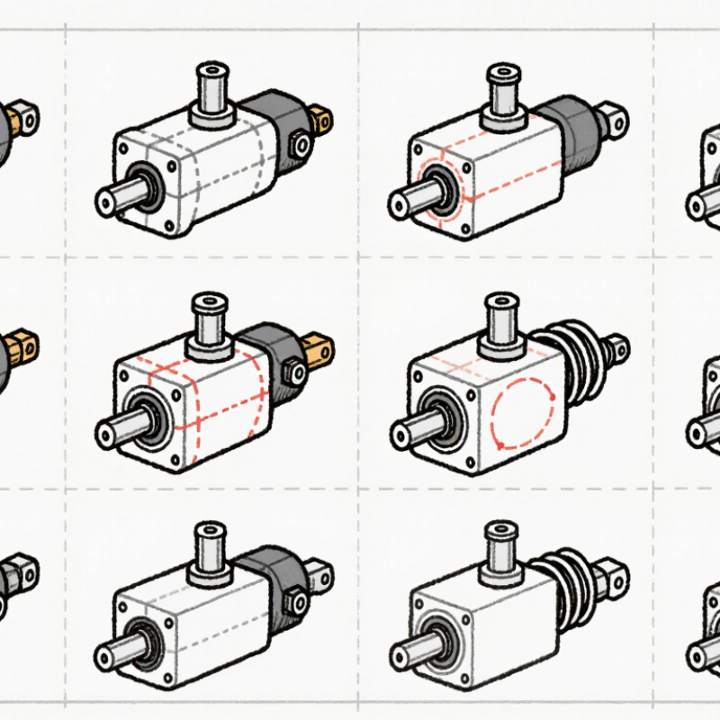
The ten common types include fixed-displacement hydraulic motors, variable-displacement motors, pneumatic motors, rotary cylinders, vane actuators, rack-and-pinion actuators, single-acting actuators, double-acting actuators, reversible motors, and limited-angle actuators. A circle often represents a motor. Arrows inside the circle show shaft rotation or fluid energy transfer. A curved arrow usually indicates rotary movement, while external ports identify working connections. Springs, pilot lines, and directional arrows add control information. Small details matter.
A single-acting symbol may show one active port and a spring-return element. A double-acting symbol normally shows two working ports. Rack-and-pinion designs often include a linear rack beside a circular gear. When reading a diagram, trace energy from the supply, through the valve, and into the actuator. Then inspect return paths and exhaust routes. On commissioning projects, I have seen a correct actuator paired with an incorrectly interpreted arrow. The result was reversed motion. I still pause when symbols look familiar. Standards can differ slightly, and a symbol may not reveal torque limits, sealing quality, or operating temperature. Those values require the technical specification, not visual guessing.

Rotary actuator symbols communicate the actuator’s motion, drive method, and operating direction. The chart compares common symbol families by their typical nominal rotation class used in pneumatic, hydraulic, and electromechanical schematics.
Quarter-turn symbols generally represent approximately 90° of rotation, while multi-turn and motor symbols indicate continuous rotary movement. Actual limits depend on the actuator design, control system, and application specification.
Rotary actuator symbols show how mechanical energy becomes angular movement. A curved arrow usually indicates rotation, while two opposing arrows suggest reversible motion. Direction matters. The arrowhead identifies the commanded turning direction, not always the shaft’s physical position. Rack-and-pinion, vane, helical, and scotch-yoke symbols may look different, but their core meaning remains similar.
Ports reveal how the actuator receives energy. Pneumatic symbols commonly show supply and exhaust connections, while hydraulic symbols identify pressure and return paths. Electrical actuator drawings may show power terminals, signal lines, and protective earth. Port labels must match the schematic legend. A familiar symbol can still mislead when labels are missing. I have seen commissioning delays caused by one reversed connection.
Control signals explain who commands movement. Solenoid lines, pilot signals, limit switches, feedback wires, and proportional inputs may appear beside the actuator symbol. A spring mark often indicates fail-position behavior after signal loss.
Dashed lines can represent pilot control or mechanical linkage, depending on the drawing standard. Read the line style carefully. It is easy to assume every thin line carries electricity. That assumption can create unsafe testing decisions.
A symbol rarely shows friction, backlash, seal wear, or delayed response. Those details require specifications and field checks. The drawing is a map, not the machine. Use measured rotation, port pressure, and signal timing to verify its meaning. Symbol standards also vary across industries, so the project legend deserves attention before installation.
Rotary actuator symbols translate motion into a compact engineering language. The basic rotary actuator symbol shows an actuator that produces angular movement. A bidirectional symbol indicates clockwise and counterclockwise rotation.
A single-acting symbol shows fluid or air movement in one direction, with a return force. A double-acting symbol uses pressure for both directions. These details matter during circuit reading.
A spring-return symbol adds a spring beside the actuator, usually showing its resting position. A vane actuator symbol uses a chamber and vane, representing limited-angle rotation. A rack-and-pinion symbol shows linear piston travel converted into shaft rotation.
A limited-angle symbol identifies movement between fixed stops. A continuous-rotation symbol suggests uninterrupted shaft movement, more like a rotary motor. An adjustable-angle symbol indicates that the travel range can be changed mechanically.
Symbol shapes may differ between standards, so I check the drawing legend before interpreting them. ISO 1219 conventions are useful, but local documentation can modify details.
My practical mistake was assuming every circular arrow meant continuous rotation. It did not.
Sometimes it only showed the movement direction. Pressure ports, spring locations, arrows, and stop marks should be read together. Small marks often carry the critical meaning. A careful technician compares the symbol with operating pressure, rotation angle, and return behavior before selecting a component.
Other variations describe the power source and control method. A pneumatic symbol may show air ports and directional flow. A hydraulic symbol commonly indicates fluid pressure and torque production. An electric actuator symbol can include a motor mark, wiring, or an electronic control link. A brake symbol suggests holding force when movement stops. A locking symbol indicates mechanical position retention. A variable-speed symbol points to adjustable rotational output. A torque-limiting mark warns that excess resistance may interrupt motion.
Position feedback symbols add a sensor connection, often drawn beside the actuator. They help controllers confirm shaft angle, not merely command movement. I check this detail carefully during drawing reviews because a command signal does not prove actual position. A feedback line may look minor. It is not.
The tenth type combines rotation with a mechanical load, such as a valve or indexing table. Its nearby arrows can show travel limits, repeated indexing, or continuous rotation. Symbol standards differ slightly between industries and software libraries. That creates mistakes. Always compare the symbol with its legend, port labels, and operating notes before selecting components.
Rotary actuator symbols translate motion into quick visual decisions. Common types include pneumatic, hydraulic, and electric actuator symbols. Others show single-acting, double-acting, spring-return, and bidirectional operation. Position feedback, braking, locking, and end-position switches complete the practical top ten. ISO 1219 supports fluid-power symbols, while IEC 60617 guides graphical symbols for electrotechnical diagrams. These standards improve consistency, but drawing practices still vary between industries.
Look for the energy source first. A pneumatic symbol usually connects to directional control valves and air lines. A hydraulic symbol suggests pressure-rated fluid circuits and return paths. Electric symbols often connect to motor starters, drives, or control modules. Arrows can indicate rotation direction. A spring mark may reveal fail-safe movement. Small switch symbols can show open and closed positions. Read every connection, not only the actuator shape.
Deloitte’s 2024 Smart Manufacturing and Operations Survey reported that 92% of manufacturers viewed smart manufacturing as a key competitiveness driver.
That pressure makes clear schematic interpretation more valuable. In field work, I still pause when a drawing uses a local symbol instead of ISO conventions. The mistake is easy: assuming a circle means one actuator type. Check the legend, signal path, torque direction, and fail position. A symbol may look familiar. The specification may not be.
Precision Cable Assemblies
16830 Pheasant Drive
Brookfield, WI 53005
Phone: 262-784-7887
Fax: 262-784-0681